INTRODUCTION
DOWNLOAD LEGACY MANUAL TS MANUAL
Waiter Legacy and Waiter TS are direct plug and play replacements for a failed or aging Intellitec ECC system.
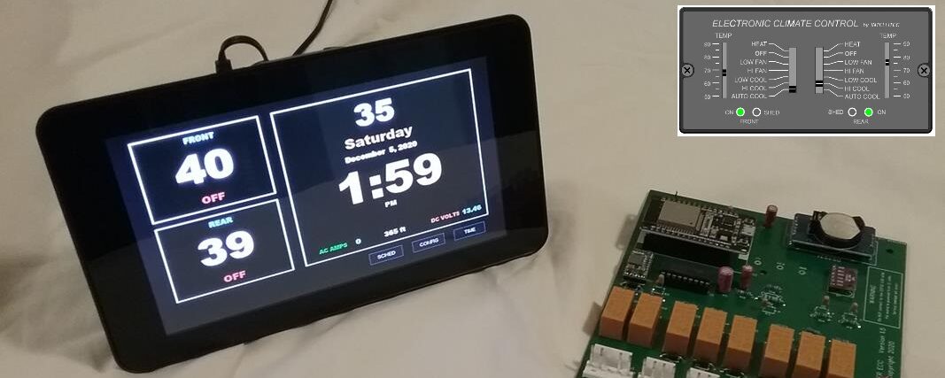
 Both Legacy kits includes two major components; 1) A new operator panel, either Legacy or TS, and 2) a replacement circuit board for the control module (CM).
Operation and control is similar to the Intellitec system with minor differences in how operational status is presented to the operator, and how temperature, shedding and A/C control functions operate.
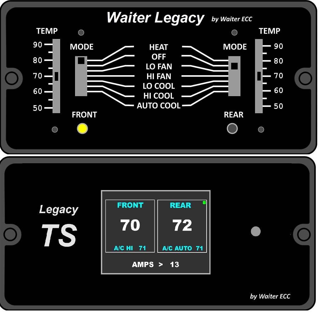
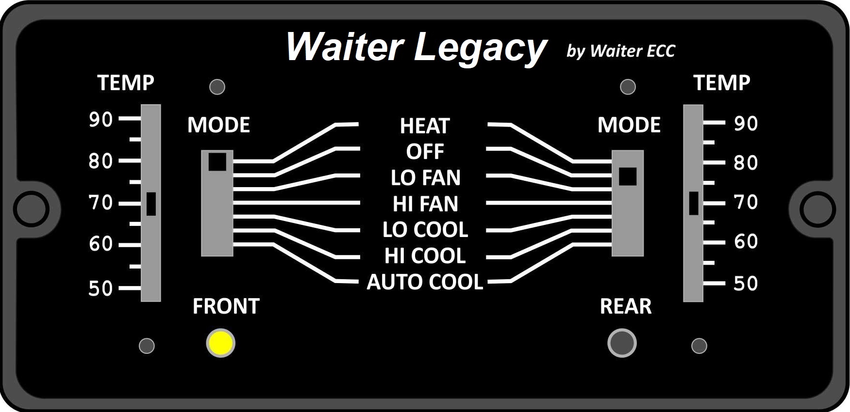
On the Legacy operator panel, operation modes and set points are selected with slider controls. System status is provided by two multi color LEDs, one for the front and one for the rear.
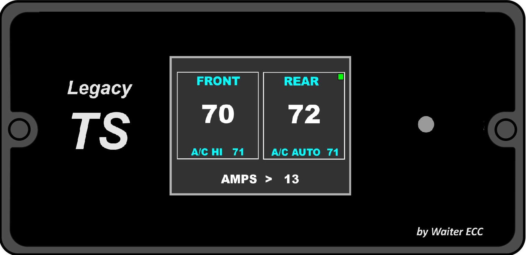
On the TS operator panel, operation modes and set points are selected using the touch screen. Status, temperatures, set points, and modes are all displayed digitally.
Control of the furnace(s) and A/C units is performed in the control module. The control module monitors the current draw (amps) and provides load shedding and power management of the A/C unit compressors as needed. The control module provides 5.6 volt power to the operator panel via the existing yellow (+) and brown (-) wires.
The operator panel and the control module communicate with each other using a dedicated wireless link similar to what you’d find in a wireless mouse or keyboard. The basic wireless channel number is set at the factory during assembly. There are four sub channel addresses that can be selected by the end user. The basic and sub channel addresses must match in order for the operator panel and control module to communicate with each other. Communications can be confirmed by observing the SIG RX LEDs on the control module and the back of the operator panel.
 TS OPERATOR PANEL (BUY NOW)

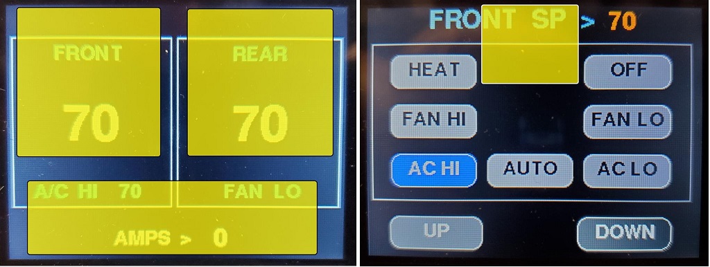
Download the OPERATION manual for full detail and descriptions. The Operators touch screen is made up of two screens, the main display screen and the mode select screen.
 Touch sensitive ares on the screens are used to make selections. The UP, DOWN and mode buttons, and the areas shown in yellow, are touch sensitive.
 After 10 seconds of no touch activity, the display reverts back to the main screen, and dims to one of four preset levels. To temporally bring the screen back to full brightness, touch on the lower portion of the main screen near the AMPS display.
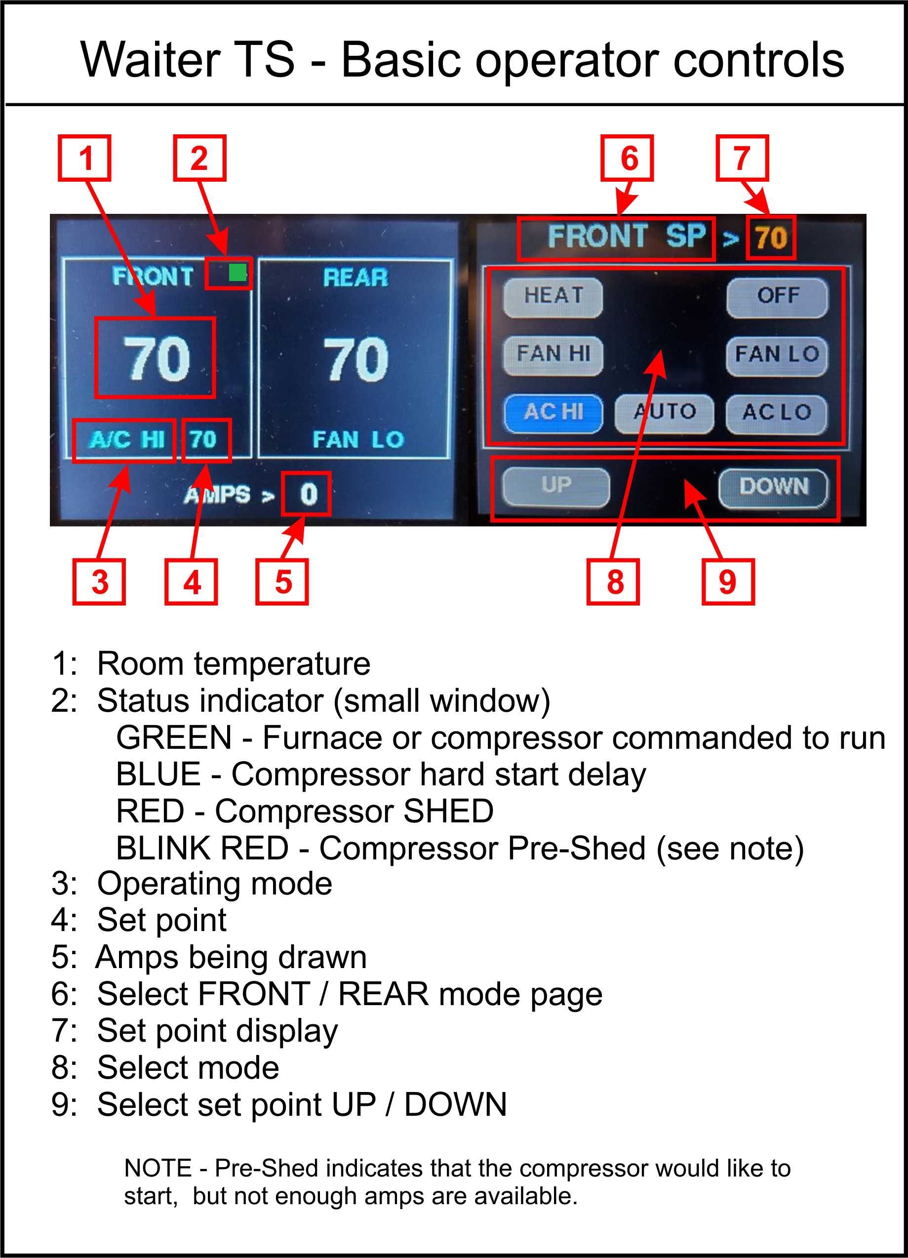
LEGACY OPERATOR PANEL (BUY NOW)
Download the OPERATION manual for full detail and descriptions. The Operators panel looks similar to its Intellitec counterpart with minor differences in appearance and functionality. The controls on the left side control the front system and the controls on the right side control the rear system. On motor homes equipped with only one furnace, HEAT mode isn’t functional for the rear system.
LED Indicators
The front and rear systems have dedicated multi color LED indicators that announce various system status and provide greater detail than the Intellitec system.
 LEGACY SENSOR TEST – TEMPERATURE / SET POINT TEST
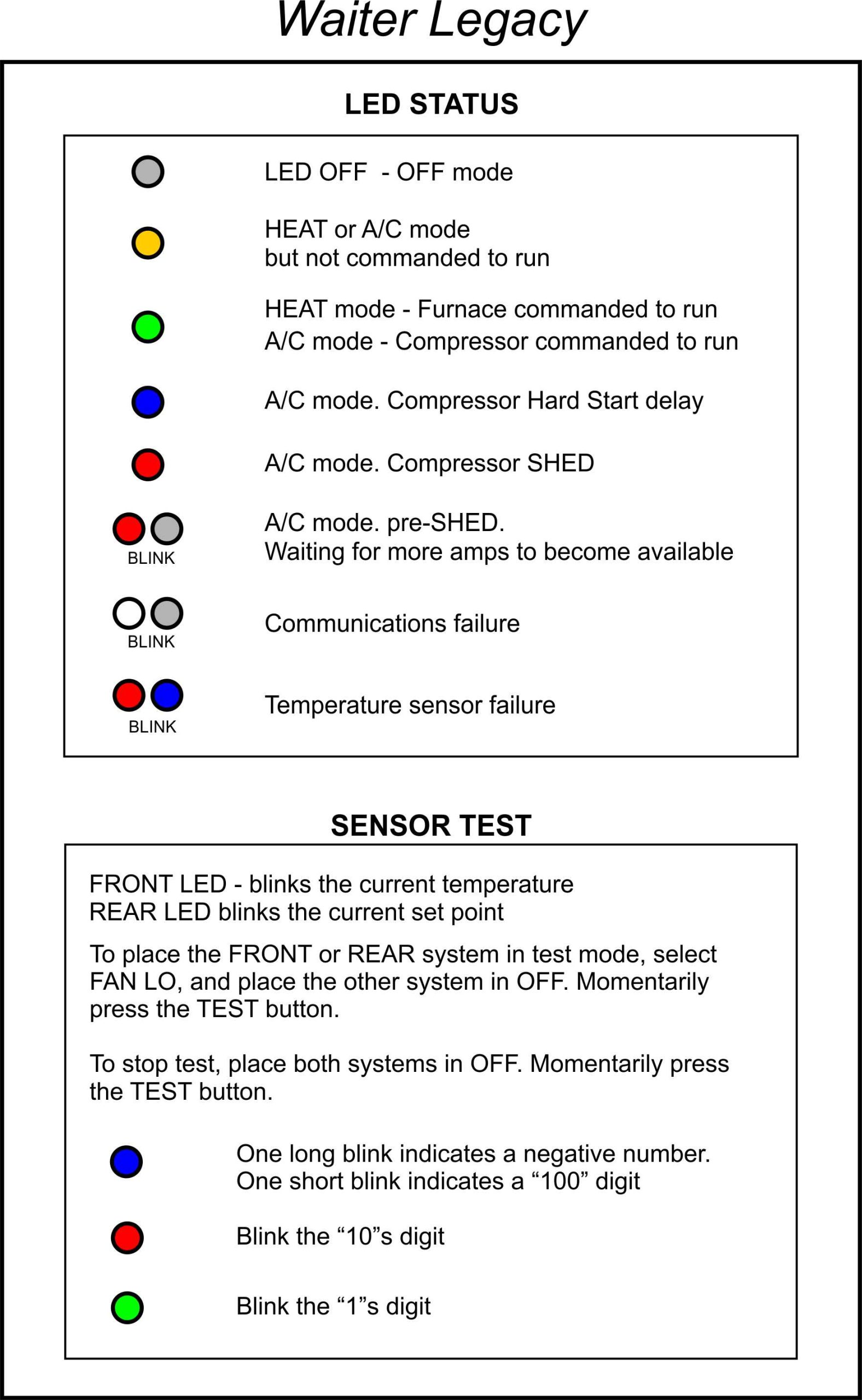
A unique feature of the Waiter Legacy system is the ability to test the temperature sensor and set point adjustment by displaying a series of blinks with the two LEDs. In test mode, the left LED (FRONT) blinks the temperature and the right LED (REAR) blinks the set point for the system that’s selected.
To select the front system for test, place the front mode switch to the LO FAN position and the rear mode switch to the OFF position. Momentarily press the TEST button on the back of the operator panel.
 The rear system is selected in a similar manner by placing the rear system to LO FAN and the front system to OFF, then momentarily press the TEST button.
To exit the test mode, place both systems to OFF and momentarily press the TEST button.
In test mode, the LED on the left (FRONT) blinks the temperature and the LED on the right (REAR) blinks the set point for the selected system.
The temperature sensor range is -99 to 199. If the temperature is a minus, the blue LED will do a long blink to signify a “-XX”. If the temperature is greater than 99 degrees, the blue LED will do a short blink to signify a “1XX” temperature. If the temperature is between 0 and 99 degrees, the blue LED will not blink.
The red LED then blinks the “10s” digit, and the green LED blinks the “1s” digit.
The “set point” range is 50 – 90 degrees. The right LED (REAR) blinks in a similar fashion to show the current set point for the selected system.
MODE SELECTION
TEMP – Sets the operating set point for both heat and air conditioning. The range is approximately 50 – 90 degrees F.
MODE – Selects the operational mode for the front or rear systems.
HEAT – The furnace is command to run when the temperature drops below the set point. The furnace continues to run until the temperature is 2 degrees or more above the set point.
If your motorhome has only one furnace, the REAR furnace mode has no functionality. If configuration switch SW4 is ON (one furnace) selecting rear HEAT will be the same as selecting OFF
OFF – Turns the system OFF.
LO FAN – Operates the A/C blower at low speed.
HI FAN – Operates the A/C blower at high speed
LO COOL – The A/C blower continuously runs at low speed, The compressor is commanded to run if the temperature is greater than set point. Compressor turns off if temperature is 2 degrees or more below the set point.
HI COOL – The A/C blower continuously runs at high speed. The compressor is commanded to run if the temperature is greater than set point. Compressor turns off if temperature is 2 degrees or more below the set point.
AUTO COOL – Blower speed changes according to the temperature. The compressor is commanded to run the if temperature is greater than set point. Compressor turns off if compressor is 2 degrees or more below the set point.
Blower high speed is commanded if the temperature is 4 degrees or more above the set point.
Blower low speed is commanded if the temperature is less than 4 degrees above set point. When the temperature drops 2 degrees or more below the set point, the compressor is commanded OFF. 30 seconds later the blower is commanded OFF.
NOTE – If the compressor is SHED during the AUTO COOL operation, the blower continues to run at its commanded speed.
IMPORTANT NOTE REGARDING NUMBER OF FURNACES:
In order to reduce costs, the same Waiter Legacy and TS operator panels are used for motor-homes equipped with one or two furnaces. Obviously if your motorhome has only one furnace (front), selecting the rear HEAT mode doesn’t do anything.
To provide more accurate functionality, a configuration switch is available on the operator panel to select one or two furnaces. This switch effects the status commands and display LED when rear HEAT mode is selected. SW4 – Number of Furnaces OFF = 2, ON = 1.
Waiter TS Number of Furnaces
When SW4 is OFF (two furnaces) , rear HEAT select button is shown when the rear MODE select screen is called up.
When SW4 is ON (one furnace) , rear HEAT select button isn’t displayed so it can’t be selected.
Waiter Legacy Number of Furnaces
When SW4 is OFF (two furnaces) , rear HEAT can be selected and the LED shows the status of commands to the rear furnace.
When SW4 is ON (one furnace), selecting rear HEAT is the same as selecting rear OFF. The LED is off and no commands are sent to the rear furnace.
SYSTEM CONFIGURATION
System parameters can be selected on the control circuit board and/or the operator panel. Configuration changes allow the user to optimize the performance of the Waiter Legacy system for their particular motor homes configuration
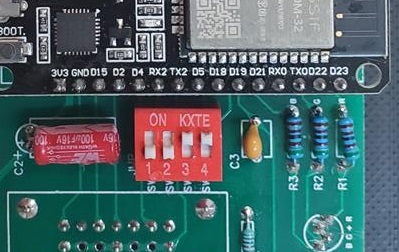
 Control Module (CM)
SW1 – ADDR1 (SW1 – SW2) OFF-OFF = 0x00, ON-OFF = 0x10
SW2 – ADDR2 (SW1 – SW2) OFF-ON = 0x20, ON-ON = 0x30
SW3 – Front A/C unit btu OFF = 13k, ON = 15k
SW4 – Rear A/C unit btu OFF = 13k, ON = 15k
SW5 – SHED sequence OFF = Rear first, ON = AUTO
SW6 – SPARE
SW7 – SPARE
SW8 – ON = Transmit maintenance data packet (normally OFF)
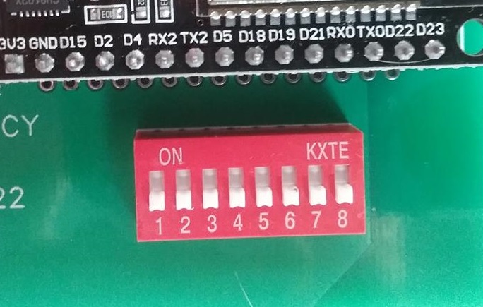
 Operator Panel (OP)
SW1 – ADDR1 (SW1 – SW2) OFF-OFF = 0x00, ON-OFF = 0x10
SW2 – ADDR2 (SW1 – SW2) OFF-ON = 0x20, ON-ON = 0x30
SW3 – LED brightness OFF = Bright, ON = Dim
SW4 – Number of Furnaces OFF = 2, ON = 1
The OP and CM must be rebooted to pick up any changes made to the ADDR switch / jumper configuration.
NUMBER OF FURNACES
SW4 on the operator panel, OFF = two furnaces, ON = one furnace.
To reduce costs, the same operator panel and control module are used in both the one and two furnace motorhomes. When configured for one furnace (JMP4 shorted) if the REAR HEAT mode is selected, it’ll be the same as selecting the REAR OFF mode. The rear LED doesn’t illuminate and there are no rear heat commands sent to the control module.
LED BRIGHTNESS
SW3 is used to configure the LED brightness. SW3 OFF = LED bright, SW3 ON = LED dim.
WIRELESS COMMUNICATION ADDRESS
SW1 (ADD1), SW2 (ADD2) on the control module and on the operator panel.
Communication between the operator panel (OP) and the control module (CM) is achieved by using a dedicated wireless link similar to what you’d find in a wireless mouse or keyboard.
The OP and CM are paired with each other before being shipped using any of the thousands of wireless base channels available. In the extreme remote possibility that two Waiter Legacy systems are in close proximity and interfering with each other, the user can select a different wireless sub channel by changing the address on the operator panel and the control module with the ADD1 and ADD2 switches / jumpers. The selected channel sub address for the OP and CM must match or they will not talk to each other.
The table below shows the sub address for the switch and jumper settings
A/C UNIT BTU
SW3 FRONT A/C unit OFF = 13k, ON = 15k
SW4 REAR A/C unit OFF = 13k, ON = 15k
Jumpers can be set to tell the system what A/C unit BTU you have installed, select 13 or 15k btu. This selection is only used for estimating the compressor current draw prior to give the command to start a compressor. The 13k btu compressor is estimated at 8 amps, the 15k btu compressor estimated at 11 amps. Actual real time current draw (amps) is used for shedding.
Pre-shed – Before commanding an A/C compressor to start, the system estimates if there are enough amps available to start the compressor. It does this by adding either 8 or 11 amps to the current amps being drawn. If the sum exceeds 28 amps, the compressor will be placed in a “pre-shed” mode and won’t start until enough amps become available.
EXAMPLE ; The system comes configured as having two 13k btu A/C units installed. The system is currently drawing 21 amps from the microwave (11amps) , A/C blower (3 amps) , Water heater (4), Refrigerator (2), and converter (1). The system wants to start the front compressor and does a pre-shed check. The sum of 21 actual amps and an estimated 8 amps for the compressor results in 29 amps. This exceeds the 28 amps maximum, so the compressor is placed in a pre-shed mode and doesn’t start.
The system continues to monitor the amps and if the microwave or water heater are turned off, there’ll be enough amps available and the compressor will start if its still needed..
SHED PRIORITY
SW5 SHED priority OFF = REAR, ON = AUTO
Shed priority provides two options on how / what A/C unit is shed. By default, the REAR setting will always shed the rear A/C unit first. The AUTO setting will alternate shedding between the front and rear A/C units.
In the REAR setting (default) if the front compressor wants to run, but there aren’t enough amps available (pre-shed), the system will shed the rear compressor in an attempt to free up enough amps to start the front compressor.
SIG RX LED
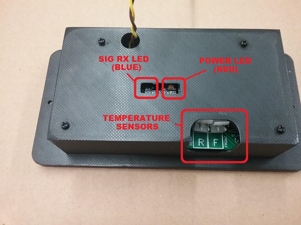
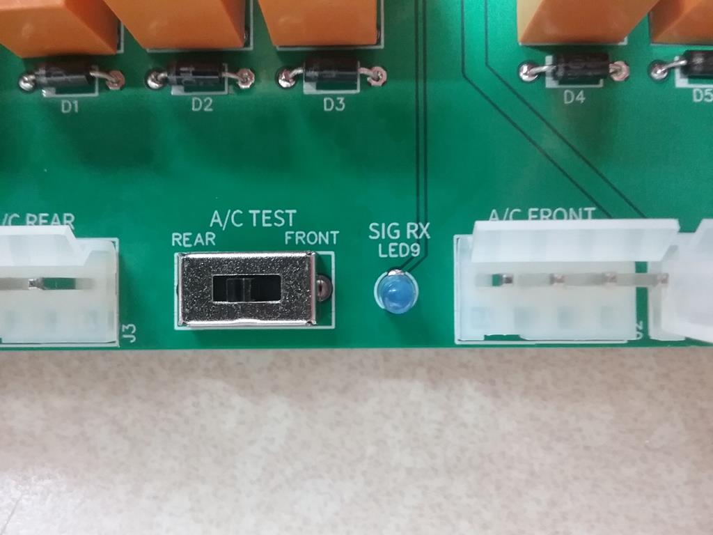 The OP and CM have a small LED indicator to signal when it receives a communications packet. Information packets are exchanged at least every ten seconds or immediately if a temperature, set point, or status changes. The blue (or red) LED on the OP or the SIG RX LED on the CM blink whenever they receive a packet.
A/C TEST SWITCH
This switch provides a quick and easy way to verify the operation of an A/C unit. This switch forces the compressor and high speed fan to run, There’s no hard start delay, no shedding, no temperature control, etc..
IMPORTANT NOTES ABOUT USING THE TEST SWITCH
1) The Waiter Legacy Control module must have 12 volts power in order for the TEST switch to function.
2) To safeguard against attempting to run the HI and LOW speed blower at the same time, its mandatory to place the front and rear systems in OFF position before using the TEST switch
3) The TEST switch bypasses shedding, hard start delay, and pre-shed functions. Before using the TEST switch, verify you have enough amps available to run the compressor without overloading the 30 amp service.
You should also allow enough time between compressor runs to allow high pressure to bleed off.
4) If you run a compressor then stop it, you must allow enough time for the head pressure to bleed down. Failure to do this could result in a large overload when attempting to restart the compressor.
WAITER LEGACY CONTROL BOARD – SIMPLIFIED DIAGRAM
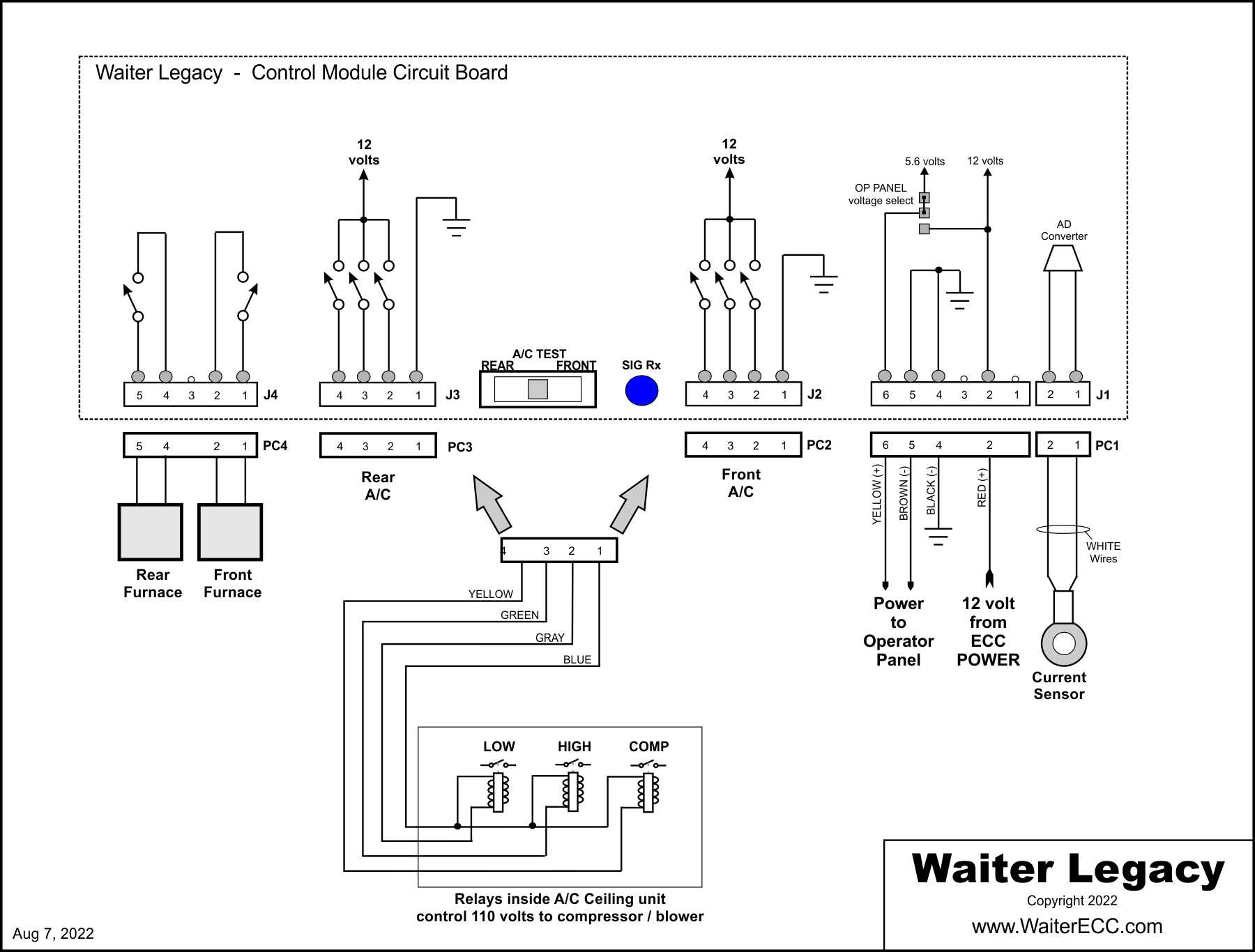
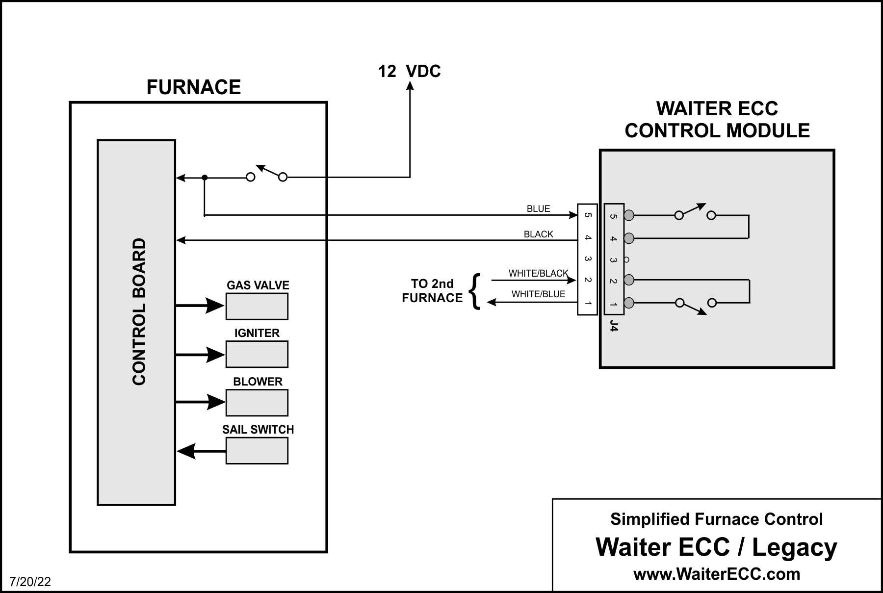
TYPICAL FURNACE WIRING
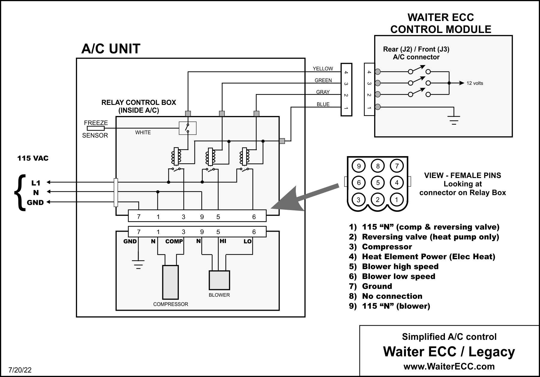
TYPICAL A/C UNIT WIRING
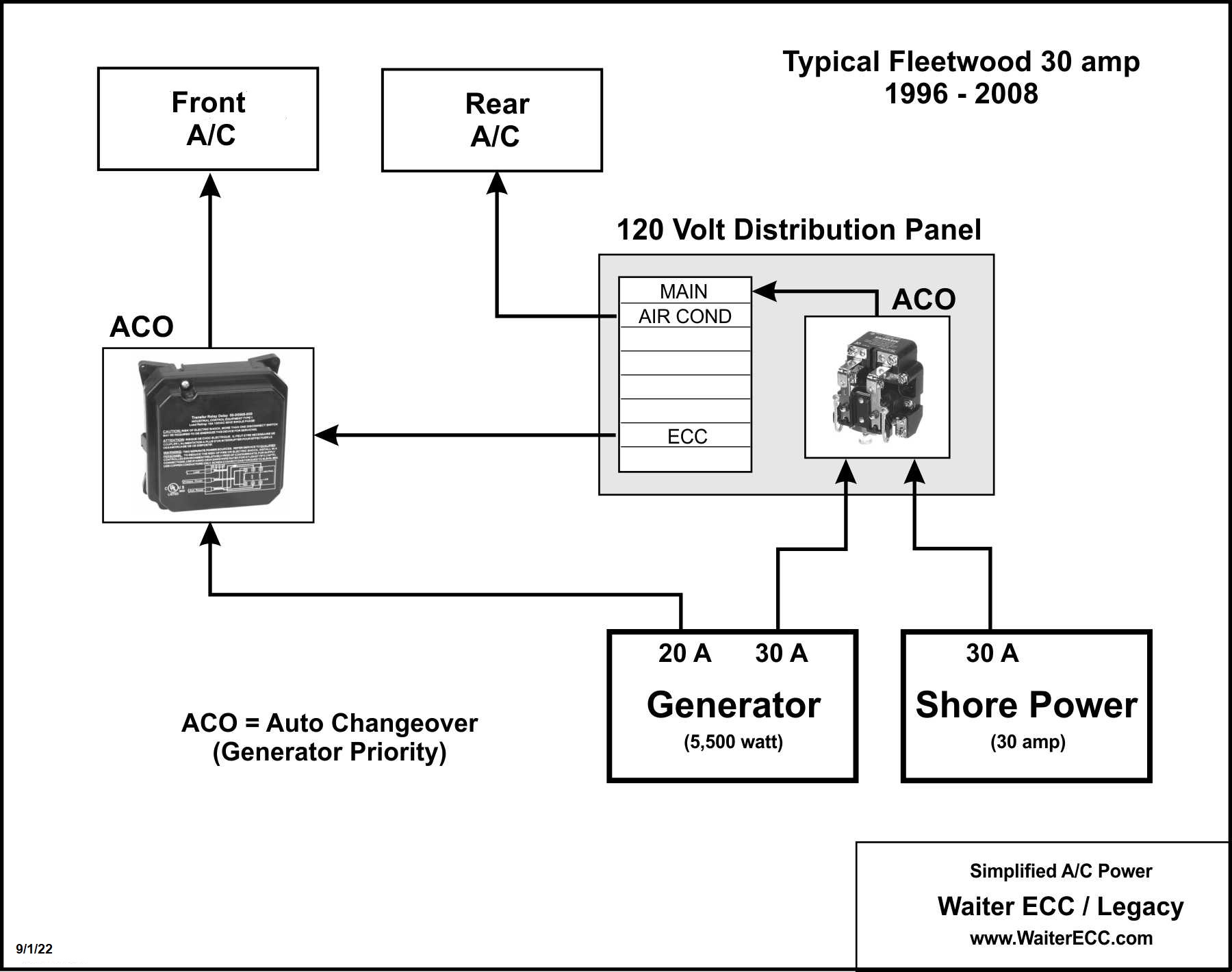
 TYPICAL POWER DIAGRAM