The Waiter ECC system provides similar functionality as the original Intellitec system, and then some. All logic and functionality is controlled within the controller module. The operator panel serves as an interface to the controller module, it receives status from the module and sends commands to the module. Communications to/from the controller module are by WiFi MQTT messages.

VERSION INFORMATION as of (Aug 22, 2022)
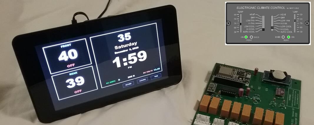
CONTROL CIRCUIT BOARD
- ESP32: MELIFE ESP-32S
- DS3231: Real Time Clock Module
- CR2032: Battery Battery for real time clock backup
- Waiter ECC Circuit board 1.11
- Waiter ECC Firmware: 2.10.4
- Arduino IDE: 1.8.15
- WiFi connectivity, DHCP to SSID > WaiterControl, WaiterControl2
- Current draw: 0.04 amps (no relays energized)
RASPBERRY TOUCHSCREEN DISPLAY
- Hardware: Raspberry pi 3A (3B, 3B plus)
- Waiter ECC Alarm / Power supply board (hat): 1.7
- Linux Rasbian: 10 (buster)
- Waiter ECC Software: 5.0.3 MQTT
- Mono: 6.8.0.105
- Visual Studio 2019: 16.5.4
- (reference) Raspberry.IO 3.1.1.0
- Current draw: 0.45 amps (booted, max brightness)
- Current draw: 0.25 amps (booted, min brightness)
- MQTT Broker (Mosquitto)
- WiFi access point,
SSID = WaiterControl or WaiterControl2
PASSWORD = ECC123456
IP = 192.168.50.10 - Remote Desktop Connection (SSH)
Username = pi
Password = waiterecc
MAJOR UPDATES:
As of Version 5.0.0, the Rpi’s uses a file system overlay and the boot partition is Read Only. This change eliminates the risk of corrupting the SD card during power cycles. With the Rpi’s SD card now being Overlaid and READ ONLY, a couple features that were incorporated into earlier versions are no longer available to the operator. The ability to change the Access Points SSID’s name and channels, and the ability for the operator to flip the screen upside down. These features can no longer be changed from the operators touchscreen, but if you want the screen flipped or use the alternate SSID, you can specify this when you place your order.
The ECC control module and the Operator interface communicate using MQTT messages over WiFi for command / status. The shift to using WiFi and MQTT make future expansion and features possible. The use of MQTT also allows any third party Operator interface, i.e. NodeRED, OpenHAB, Home-Assistant, etc, to easily work with the Waiter ECC system. If it can send and receive MQTT messages , it can control the Waiter ECC systems.
The heart of the Operator control touch screen is the Raspberry Pi, a powerful mini computer. The Rpi and operator touch screen serves four functions:
1) Software called MQTT broker is installed (Mosquito). The MQTT broker is like a telephone switchboard for messages. It receives messages from many different users in the form of a “topic” and a “message”. It then sends the messages out to anyone who “subscribed” to receiving any particular “topic”. The MQTT broker system is popular among automation control systems like Node-RED, OpenHAB, Home Assistant, etc, and serves as the heart of the Waiter ECC System.
2) The operators touch screen and corresponding application allow the operator to configure and control the Waiter ECC Control module. The application software also has the ability to control several future add-ons; Power Gear leveler control, generator control, a water heater controller, and a custom residential refrigerator control. ALSO, additional optional operator interfaces can easily control the ECC and other systems. Example: I have the main Rpi touch screen in the bedroom and another operator touch screen in the living room. Both touch screens are identical, except one (the bedroom) acts as the main controller. The other acts as a remote (slave).
3) The Rpi also acts as the main wifi access point for the Waiter ECC system: It has a static IP address of “192.168.50.10”, The WiFi SSID is “WaiterControl” or “WaiterControl2”. All Waiter control modules and operator interfaces automatically connect to this SSID via WiFi and receive their IP address from the DHCP server on the access point.
4) OEM temperature sensor interface. The Rpi doesn’t have a stock analog to digital (A/D) converters on it, so a special circuit board (hat) was designed that incorporates an A/D converter used to read the two original thermistor temperature sensors. A program on the Rpi called OEM_Sensor.py starts at bootup and runs as a system service. This program communicates with the A/D converter chip mounted on the hat (MCP3002). The front and rear temperatures are read and converted to MQTT text messages. These messages are sent to the onboard MQTT server, where they’re forwarded to the controller circuit board.
CLICK HERE to download the latest Technical Manual.
NEW STUFF COMING SOON
Water heater control – variable set points and schedules. OEM control is normally set at 140 degrees and cannot be changed. I allow you to set the temperature between 80 – 140 degrees. Also there are four schedule lines that can be programmed, i.e. set the thermostat for 130 deg at 7am for the morning shower and dishes. then turn it back to 90 degrees at 9am.
Refrigerator – I built a new control module for my residential refrigerator. Although its stand along, it can also be controlled by the Rpi Operator screen.
Generator and Leveler controller. I’m working on a generator controller and a leveler controller that also can be controlled with the Operator interface. These also connect via wifi and use MQTT messages for command/status.