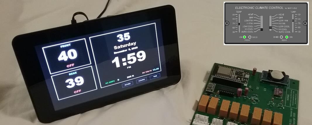
The Waiter ECC is a direct plug and play replacement for older Intellitec ECC systems providing all the functionality of the original Intellitec system, plus several new features that brings a 20 year old system up to date. The system is made up of two main components, the custom control circuit board and the operators touchscreen display assembly.
 The kit comes complete with everything needed to perform a basic retrofit: Kit includes:
- Instruction guide
- Custom control circuit board
- Operator touchscreen assembly
- One external temperature sensor
- One power switch
- Template for mounting touchscreen to wall
- Valcro strips for mounting to wall (if needed)
- Yellow and Brown heat shrink for insulating connectors (if needed)
- Quick disconnect lug connectors for power switch (if needed)
- Optional Wall Mount Plate
BASIC INSTALLATION PROCESS
- Photograph old installation, especially plug connections.
- Remove the 5 amp, 12 volt fuse that supplies power to the ECC system
- Remove old control module and operator control panel.
- Install the ON/OFF switch in the 12 volt line that feeds the control module
- Using the template or optional Wall Mount Plate as a guide, cut the wall opening for the operator touchscreen. Test fit. Use Vacro strips to secure touch screen to wall.
- On the back of the touchscreen, plug in the two temperature sensors.
- On the back of the touchscreen, connect the two 12 volt power wires Yellow to Yellow (+) and Brown to Brown (-).
- Disassemble the control module enclosure and replace the circuit board.
- Reconnect the connectors to the new circuit board
- Re-insert ECC fuse, turn 12 volts ON.
- Verify system boots up, verify configuration, set the time.
CLICK HERE to download the latest detailed installation manual (Aug, 2021).
NOTE: If your motor home has a A/C Fan Bypass Controller installed, it must be completely disconnected as it will not allow proper operation of the Waiter ECC system. Unplug the two 4 pin connectors from the A/C Fan Bypass Controller and plug these directly into the Waiter ECC Control Module. To read more, look in APPENDIX A of the Installation Manual
