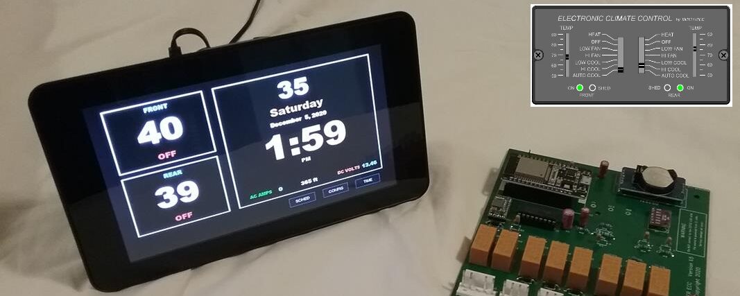
Prior to about 1997, Fleetwood used an early model Intellitec ECC, These can be identified by the operator panel , part numbers, and how the temperature sensors are mounted. If you have this older version, you’ll need to select the EARLY VERSION when you order your Waiter ECC system. Read through the information below before ordering an EARLY VERSION, verify that you really do have an early version by comparing your part numbers. The wall mount thermostat and the control module will have part numbers 00-003XX-XXX. Newer model units will have part numbers 00-005XX-XXX and 00-008XX-XXX. If you’re not sure what upgrade kit you need, send me a message via the CONTACT form that’s at the bottom of the ABOUT US page.
The EARLY MODEL upgrade kit comes with two new temperature sensors, connectors, and wire nuts. You’ll need to replace your original wall mount sensors with these new sensors, and replace the two original sensor plugs with the two new sensor plugs. The new sensors and plugs have about 9 inches of wire. You cut the wires to the old sensors and plugs about 6 inches back, then use the enclosed wire nuts to splice the new sensors and plugs into the existing wires. A small instruction sheet is also included in the kit.
WHY DO YOU NEED THE UPGRADED 10k SENSORS AND PLUGS – Three reasons:
1) Early Intellitec systems used a 2.2k ohm thermistor sensor, later models used a 10k ohm version. Waiter ECC is looking for the 10 k ohm sensors. Waiter ECC will not function properly with the old style 2.2k sensors.
2) The original sensors were mounted flush to the wall with the sensing element actually located inside the wall. These probably did a better job of measuring the temperature inside the wall than they did measuring the temperature of the room. The new style sensors have a spacer and the sensor element protrudes out from the wall by about 5/8 of an inch.
3) The two original sensor plugs that plug into the back of your early model Intellitec wall thermostat are to small and won’t fit with newer Intellitec or Waiter systems.
The new style sensors are very accurate and responsive to temperature changes in the room. If you have an ohm meter you can easily verify what sensors you have by measuring the resistance of the sensor when its unplugged from the control head. If the room temperature is about 75 degrees, the 10k will read about 10k ohms, the 2.2k will read about 2.2k ohms. (There is a chart for the 10k temperature to resistance HERE).
HOW TO IDENTIFY THE EARLY MODEL SYSTEMS
Look at the part numbers, sensor pin color and type, and the sensor and how they are mounted. If you have any questions, send me a message via the CONTACT form that’s at the bottom of the ABOUT US page.

Early model Control module part number 00-00329-100

Early model Operator panel part number 00-00330-100. Note the blue and red color bands that show the temperature slide setting. The new style has temperature numbers instead of the blue/red bands.

Early model temperature sensor connector on the back of the thermostat were red color, newer style will be a little larger and are white in color

Temperature sensor connector on Intellitec control panel
INSTALLING UPDATED TEMPERATURE SENSORS
The Waiter ECC version of the 10k sensor looks similar to the new style Intellitec sensor. We 3D print the sensor enclosure and assemble the sensor element inside the enclosure. When mounted, the sensor protrudes out from the wall about 5/8 of an inch. You’ll need to replace both the front and rear sensors and the two sensor plugs that goes on the back of the wall thermostat.
1) Remove the screws and pull the sensor and wires out from the wall. The sensors usually have 12-18 inches of wire, then are butt spliced to the wires that run to the operator panel. Cut the wires at the butt splice.
2) Using the wire nuts splices included in the kit, splice the new sensor into the wires that go to the operator panel.
3) Push the wiring back into the hole and screw the new sensor to the wall where the old sensor was located.
4) At the operator panel; One at a time so you don’t get wires mixed up, cut the old connector off about 2 inches from the connector.
5) Using the wire nut splices, splice the new connector onto the wires that come from the sensors.
6) Repeat steps 4 and 5 for the other connector.
The new sensor plugs will now plug into the back of the Waiter ECC, Waiter Legacy, or Waiter Legacy TS operator panels.
.

